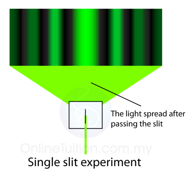
In fact, each ray from the slit will have another to interfere destructively, and a minimum in intensity will occur at this angle. A ray from slightly above the center and one from slightly above the bottom will also cancel one another. Thus a ray from the center travels a distance λ/2 farther than the one on the left, arrives out of phase, and interferes destructively. In Figure 2b, the ray from the bottom travels a distance of one wavelength λ farther than the ray from the top. However, when rays travel at an angle θ relative to the original direction of the beam, each travels a different distance to a common location, and they can arrive in or out of phase. When they travel straight ahead, as in Figure 2a, they remain in phase, and a central maximum is obtained. (Each ray is perpendicular to the wavefront of a wavelet.) Assuming the screen is very far away compared with the size of the slit, rays heading toward a common destination are nearly parallel. These are like rays that start out in phase and head in all directions. According to Huygens’s principle, every part of the wavefront in the slit emits wavelets. Here we consider light coming from different parts of the same slit. The analysis of single slit diffraction is illustrated in Figure 2. In contrast, a diffraction grating produces evenly spaced lines that dim slowly on either side of center. Note that the central maximum is larger than those on either side, and that the intensity decreases rapidly on either side. Figure 1 shows a single slit diffraction pattern. Light passing through a single slit forms a diffraction pattern somewhat different from those formed by double slits or diffraction gratings. (b) The drawing shows the bright central maximum and dimmer and thinner maxima on either side.

The central maximum is six times higher than shown. Monochromatic light passing through a single slit has a central maximum and many smaller and dimmer maxima on either side. Sorry but I do not have experience with such gratings.Figure 1. In case you have refractive gratings then I do not know if the formula stays the same or on top of it is snell's law applied. The angles does not change however the shape and clarity does. Beware non linear tracks have major impact on the diffraction result. That I use for my home made spectroscopes. Looks like formula and simulation is matching real gratings made from: Diffracted rays length indicates the m as You can see some overlap. The horizontal white line going from left to the grating is the light source. Here preview for d=1.6um (grating from CD) simulation based on this:ĭone using simple 2D ray casting and RGB values of visible spectrum Here simple C++ computation void grating(double lambda,double d,double a) //, , M is the degree of diffraction ( m=0 is simple reflection)ĭ is distance between tracks of grating in. The well known formula for reflective gratings is: sin(a)+sin(b)=m*lambda/dĪ angle between grating normal and incoming light in ī angle between grating normal and diffracted or reflected light b in So I made an simulation to show and prepare new construction configuration for my devices. The diffraction angles did not match my angular tweakables with new gratings so I needed to see where exactly the usable spectrum will be reflected.

Just a few days ago I needed exactly this while in process of upgrading my spectroscopes from CD/DVD to BluRay gratings.


 0 kommentar(er)
